Warpage Analysis for Rotational Parts
We numerically predict a part’s warpage (shape distortion) at the design stage; then, using the deviation map, we reshape the surfaces with smart features (beads, bosses, flanges, curves), optimize the mold parting line and rib layout independently, and re-route load paths. This pulls flatness, bowing and twist back within tolerance.
Main causes of warpage in rotational molding
If regions of the part do not cool at the same time or rate, some sections solidify earlier than others. Early-cooled areas shrink more, while late-cooled areas shrink less. When the part is demolded, the stored internal stresses are released and pull the part toward the faster-cooled side.
Such temperature differences often come from poor mold placement: in shadowing molds the outer surfaces cool quickly and inner surfaces slowly. Design traps—closed pockets, thick flanges, or uneven mold construction—can also confine heat locally.
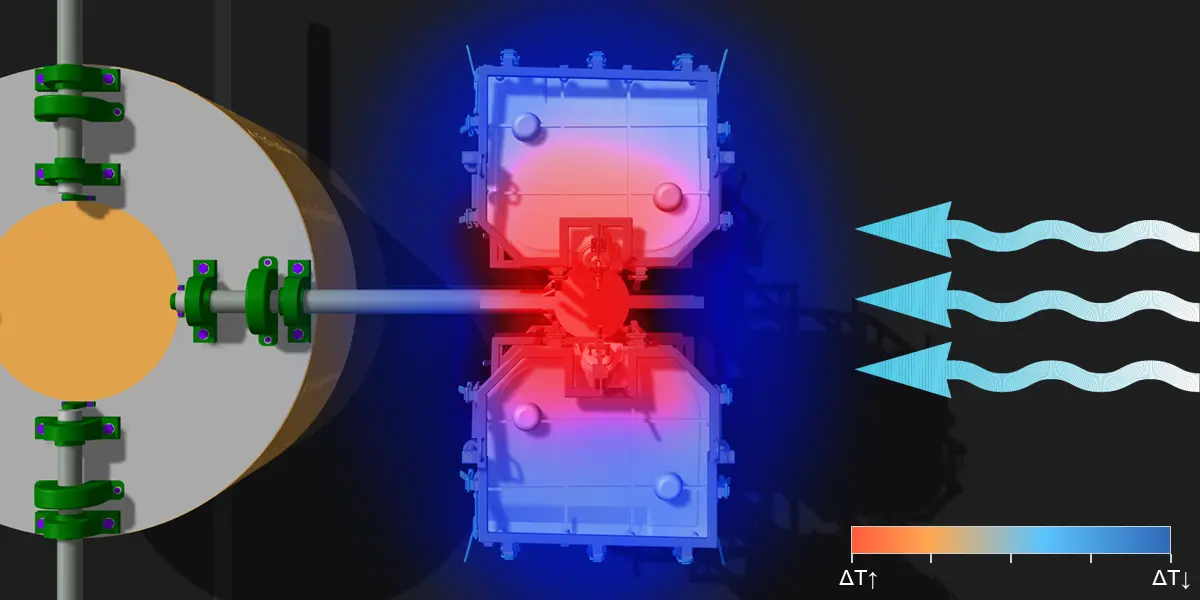
Local ΔT → different shrinkage; non-uniform tension/compression through the wall.
Thick regions retain heat longer and cool slowly; thin sections cool faster and shrink earlier. The time lag in cooling creates internal stresses. Thick areas that are still cooling pull on already-solidified thin areas, distorting the form and producing warpage.
By process nature, powder tends to accumulate around intricate features where it contacts the mold more, creating thick zones, while wide flat surfaces—especially mid‑panels—tend to be thinner. Sharp design corners disrupt flow, causing material to pile up at inner radii and recede from outers. Uneven mold rotation or wall thickness also worsens distribution.
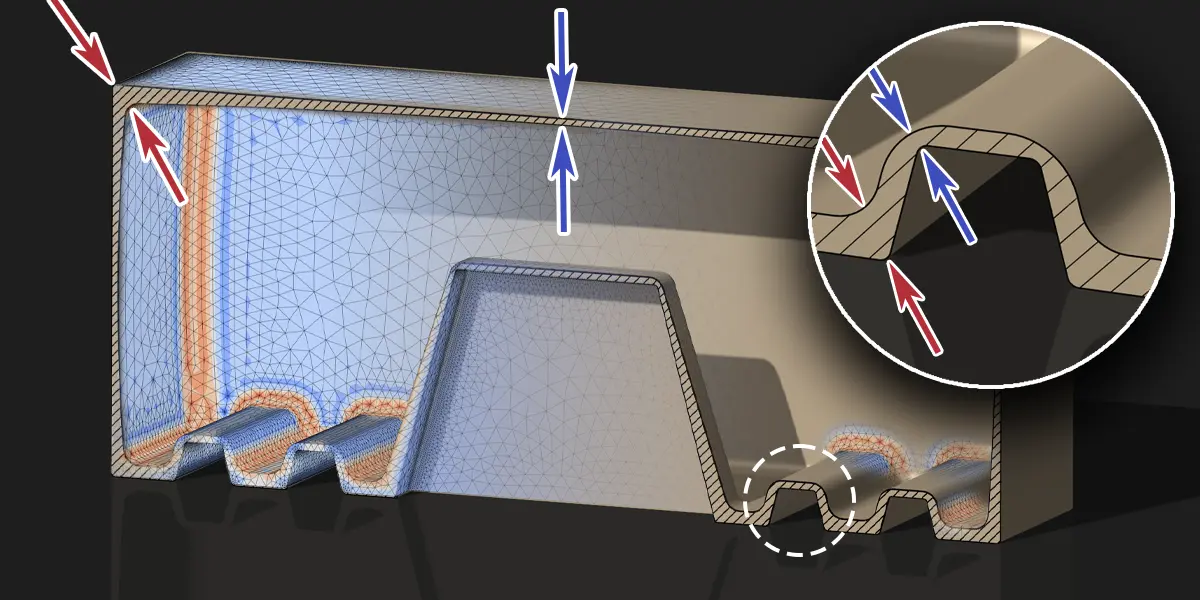
∇T ≠ 0 → Δε_th = α·ΔT → asymmetric tension/compression through the wall → bending (warpage).
If one side carries more features while the opposite side is plain, the two sides will not shrink equally. The heavier side (more mass/area) cools later and may shrink a bit more; the other side finishes earlier. Upon demolding, this imbalance produces a net bending/torsion.
Typical sources: placing holes/windows all on one side; concentrating ribs, flanges or carriers on one face; one‑sided rib patterns; large fillets on one face vs. sharp breaks on the other; shifting the centroid off axis; asymmetric shoulders/arches/curves. Even at equal thickness, shape/mass imbalance can cause differential shrinkage and shape errors.
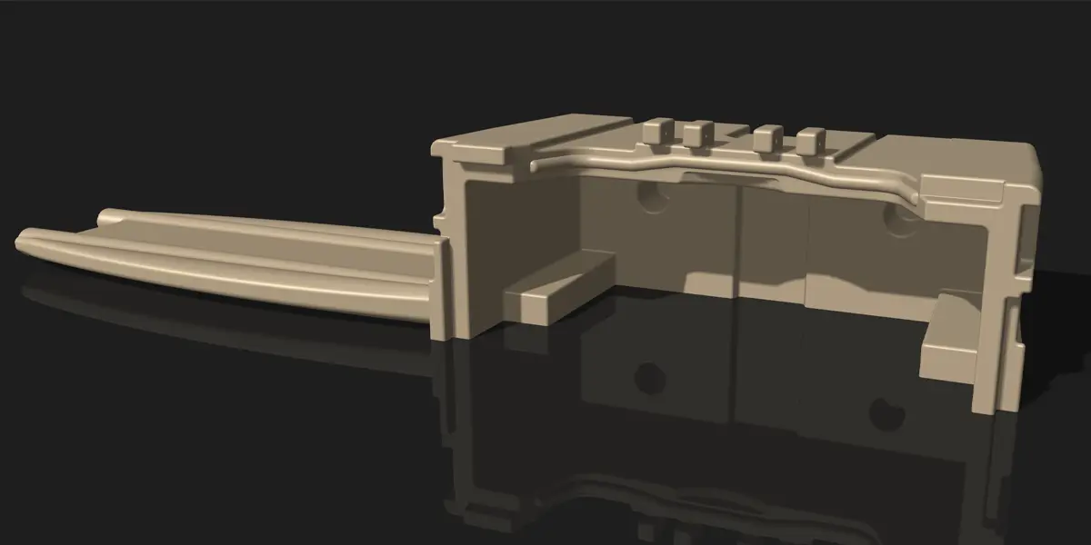
Mass/stiffness concentrated on one side → centroid/load paths shift; the shell tends to bend.
No matter how precise, a parting line is not a monolithic inner surface like the rest of the mold. Edge geometry, micro‑roughness and inevitable dust raise friction along this band. As the part cools, the surface can move less there—acting like a small brake.
Result: less shrinkage along the parting line and more elsewhere. After demolding, the difference shows up as lip bending and waviness along the edge.
Constraint at the parting line → less shrinkage there; more elsewhere.
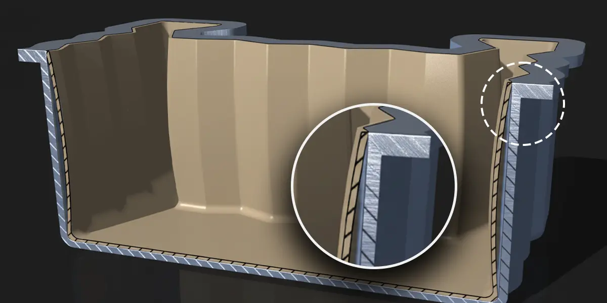
When a part combines plastics with metal inserts, foams or different plastic layers, each material wants to shrink according to its own nature during cooling. Because coefficients of thermal expansion (CTE) and stiffness differ, so do the shrinkage rates.
Stresses accumulate near the interfaces and reveal themselves on the part: local sink or bulge around inserts, ovality in circular flanges, waviness along layer transitions. If these internal pulls bias one direction over the whole, noticeable warpage is inevitable.
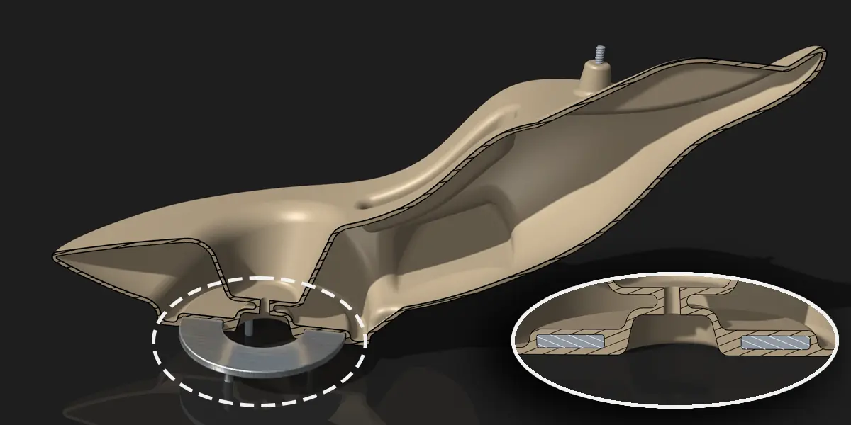
Δα in material pairs → different cooling shrinkage; stress/deflection around joints.
During cooling/solidification, polyethylene partially detaches from the mold, creating a thin air layer. Compared to metal contact, heat transfer drops markedly; the detached surface cools later and shrinks differently.
After demolding, these temperature/shrinkage differences are released and appear as one‑sided bending/dishing.
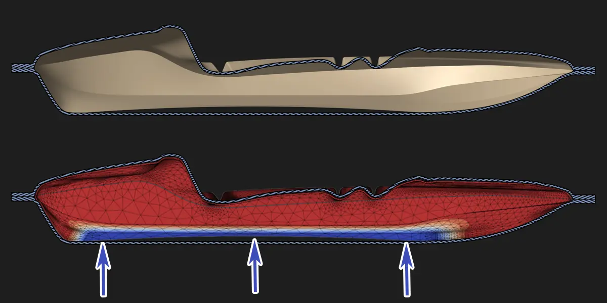
Early detachment → air gap between part and mold → local cooling anomalies and bend foci.
Venting must expel expanding gases during heating and admit air during cooling to avoid vacuum. But if incoming cool air is directed at a specific region, that region solidifies earlier and shrinks more. If venting is insufficient, internal pressure drops during cooling while outside pressure stays higher; broad, thin panels can be pulled inward.
Faulty venting thus causes large surfaces to dish/bend toward the air‑inlet side, while vacuum effects leave permanent inward collapse on wide flat panels.
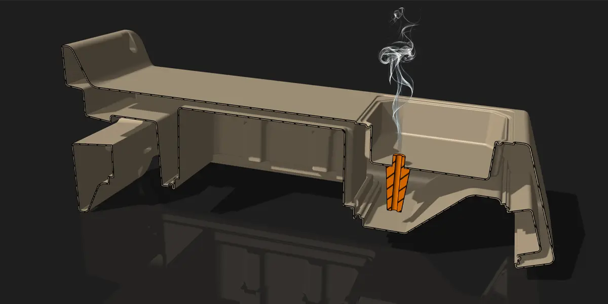
Venting imbalance → local ΔT/ΔP differences.
Analysis: Coupled Thermal → Structural
Based on the inputs below, we solve the transient thermal field during cooling to obtain shrinkage strains; we then map them into a structural analysis to predict the part’s shrinkage/warpage behavior.
- Wall thickness distribution (including critical regions)
- Features that amplify or reduce sink/warpage
- Mold construction effects on cooling
- Cooling and venting
- Demolding temperature/time
- Material data: E(T), α(T), ρ(T), k(T), cp(T)
- Thickness + cooling + air‑gap → ΔT(t) → εᵗʰ(t) → mapped to structural → free‑state warpage.
In real production, shrinkage and warpage of a rotationally molded product never come from a single cause. From loading powder into the mold to seeing the finished tank in the field, the process roughly works like this:
- The material properties of the resin, and even the fineness and homogeneity of the powder, directly affect shrinkage.
- In most cases, due to mold geometry and how the molds are positioned inside the machine, a non-uniform temperature field develops inside the mold during production.
- The magnitude of the stresses that build up during processing depends on many parameters such as mold design (note: the mold, not the product), oven settings and rotation schedules.
- After demolding, the part:
- sometimes has certain faces in direct contact with a cold concrete floor,
- sometimes has specific faces exposed to air flow and wind,
- and sometimes is stacked on racks, one tank resting on another.
In other words, most manufacturers cannot cool parts in a perfectly controlled, climate-conditioned environment. Cooling rate, which faces cool first, where air flows, and the thermal conductivity of the support surface are all environmental factors that influence the final shape. Two tanks coming from the very same mold may still not be identical, purely because of these differences.
In theory, if we knew every single detail mentioned above (oven curves, temperature–time history at every point of the mold and part, crystallization behavior, stresses generated during curing, storage conditions, etc.) without any uncertainty, we could calculate exactly how much the product will shrink and bend, down to the last millimeter. In practice, however:
- A large portion of this data is never measured or simply varies from batch to batch.
- Material suppliers often do not have (or do not publish) detailed data for crystallization and viscoelastic behavior.
- Describing the full set of environmental conditions after demolding for every single part, on a part-by-part basis, is practically impossible.
For this reason, the analysis we perform here is not a “simulation movie” that claims to copy reality 1:1. It is a engineering model that captures the physical logic of shrinkage and uses it to guide design decisions.
What does this analysis actually do – and what should you expect from it?
With this work we aim to:
- Highlight the regions where shrinkage and warpage are most likely to concentrate,
- Compare different design options (ribs, corner radii, wall-thickness distribution, windows and drain openings, etc.) against each other,
- Provide quantitative evidence to the designer by saying: “In this geometry the risk of local shrinkage is higher in region X; with this alternative, the same risk is reduced”,
- Match the deformation patterns observed in the field with the tendencies seen in the model, so that we can more accurately decide what to change in the next design iteration.
So this analysis does not claim:
“In every production run, this tank will shrink by exactly 8.3 mm at this precise point.”
Instead, what it does is:
“In this design, swelling or shrinkage in region X is higher than in the alternatives; if we add a rib here or adjust the wall-thickness distribution, the shrinkage becomes significantly lower.”
Therefore, these results gain their full meaning only when combined with measurements and field experience that we use as calibration references. They provide a rational basis for answering the question: “Which design changes will keep shrinkage and warpage under better control?” and they offer you a physics-based design process instead of a “try-and-error in the dark” approach.
Scope & Deliverables
What do we analyze?
- Wall thickness distribution, corner/rib ratios
- Cooling method and direction (air, water)
- Mold–part detachment effects and transient temperature field
- Post‑demolding flatness, bow and twist
Our deliverables
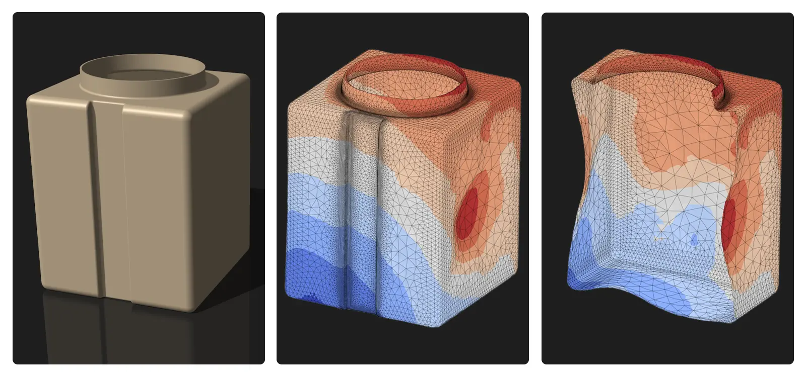
- Color maps: thickness, temperature, warpage (scaled shape)
- Comparison tables: scenario‑wise warpage metrics
- 1‑page executive summary and notes annotated on the CAD model
- Design & process recommendations (fillets, ribs, cooling)