Mechanical Strength Analyses for Rotational Parts
We numerically verify real service loads and quantify the structural strength of rotational parts. Weak regions are identified before production and reported with targeted reinforcement/wall-thickness recommendations.
Avoid unnecessary weight; reinforce only where it matters.
Shorten prototyping cycles; get closer to the right design on the first attempt.
Expose weak spots before tooling and production.
Design Under Real Loads
We compute where and how much the part deflects under load and how stresses distribute. Stability risks (local in/out buckling) that can occur on wide flat panels are evaluated in the same scope.
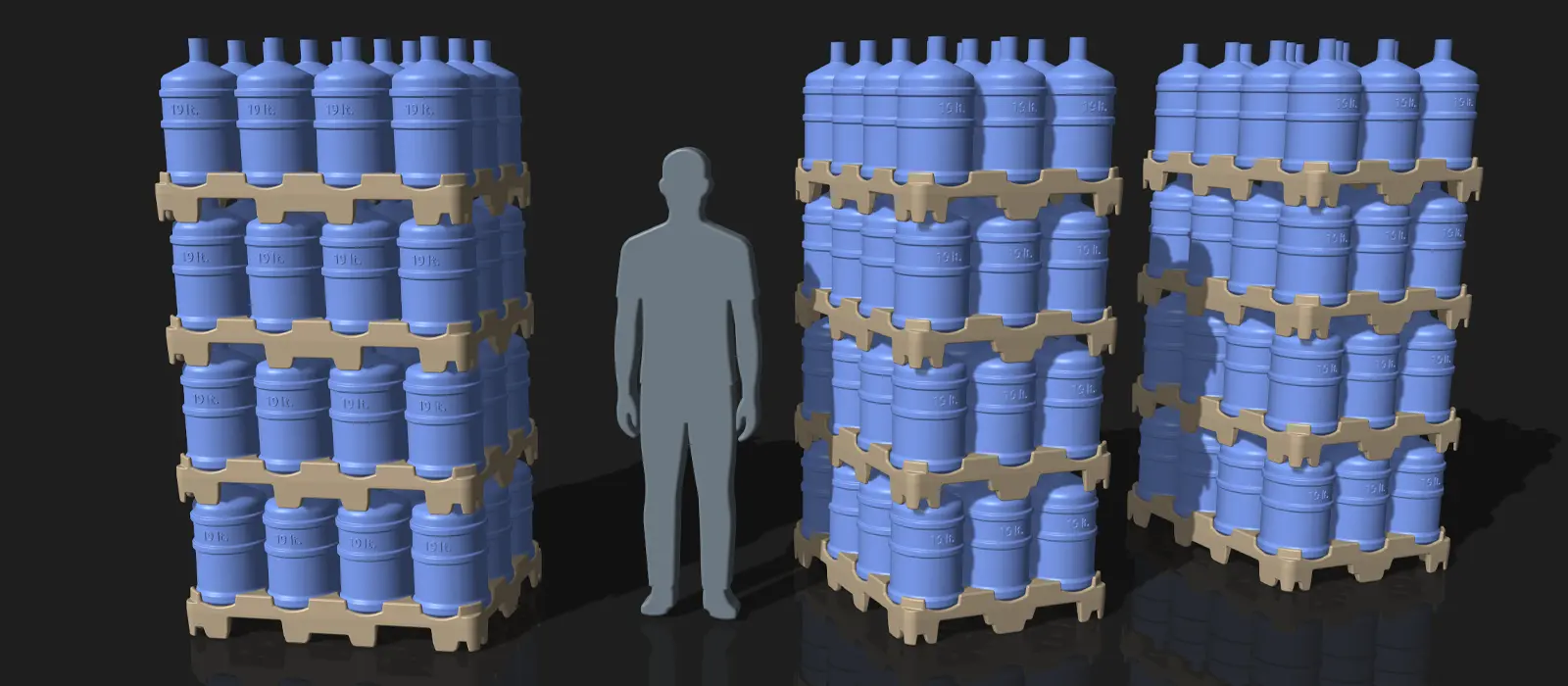
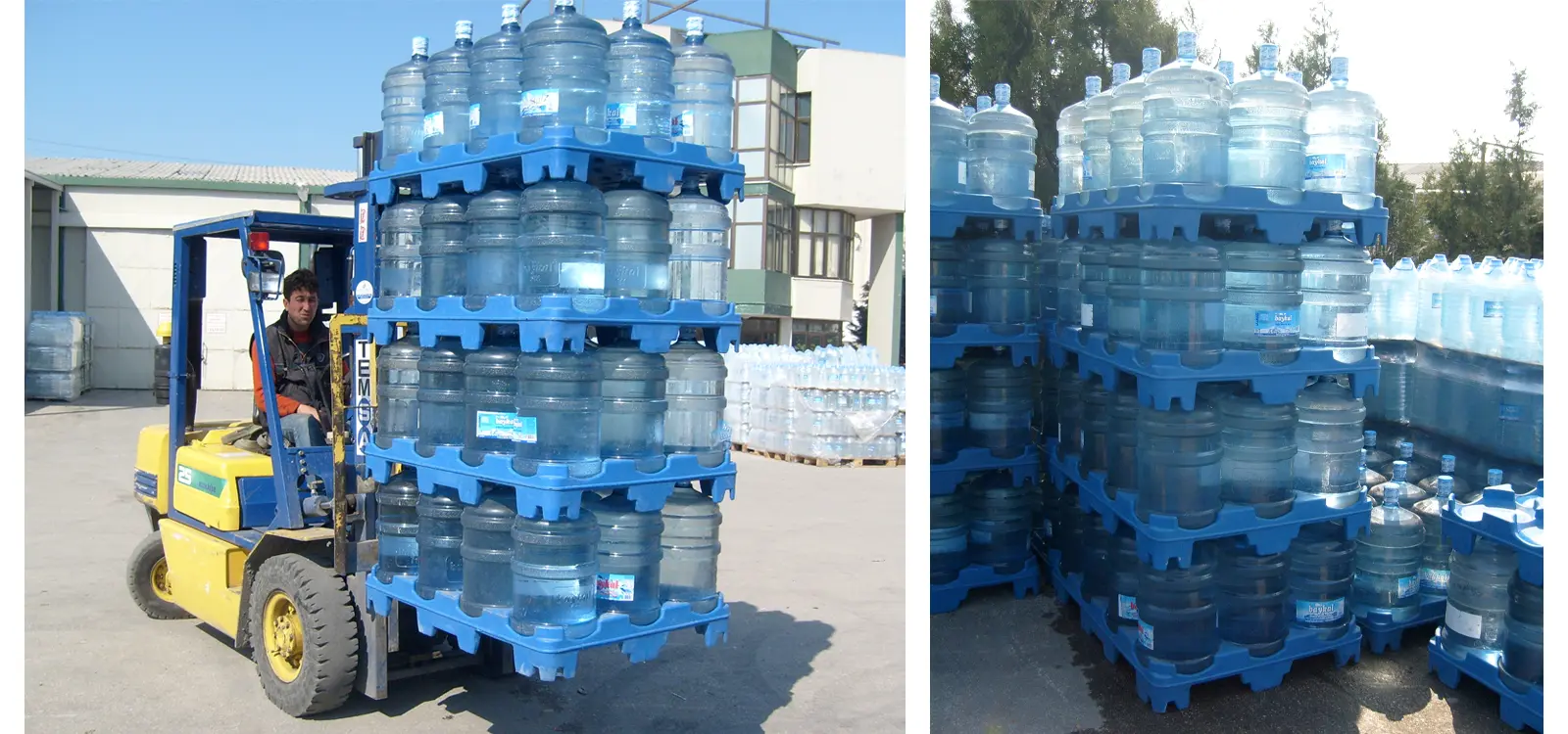
Our customer needed a polyethylene pallet for 19-L water jugs that inspires confidence in the field while avoiding unnecessary weight in transport. Using real stacking and handling scenarios we built a data-driven lightweight-vs-strength balance; we co-optimized crack-free service, smart reinforcement and manufacturable geometry.
- Use scene: multi-stacking, forklift handling, transport.
- Risks: contact-driven local overstress and structural failure (crack/break); slip and tip-over; long-term effects (creep, temperature, UV).
- Checks: load paths and contact areas; support/footing points; global deflection (u, mm) and stress distribution (σVM, MPa); stability on wide/flat panels; slip with friction and misaligned-stack scenario.
- Objective: safe handling at minimum pallet weight; keep fracture and permanent set below limits; ensure slip/tip safety; stability margins; manufacturable and economical geometry.
- Design variables: foot placement & geometry; ribbing; global wall thickness + targeted distribution (smart reinforcement around contact/support zones).
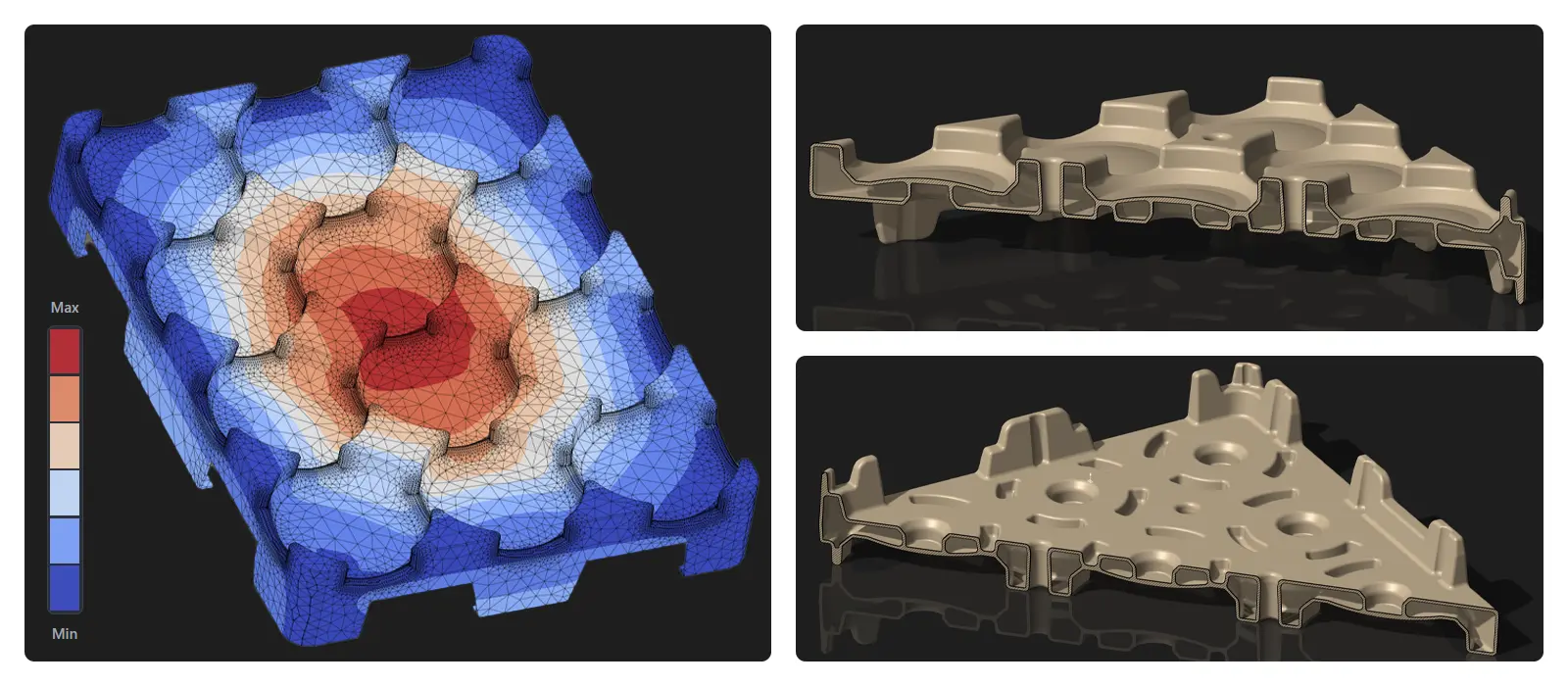
The short-listing process involved comparing foot types and thickness distributions under identical loads. Critical regions were solved with locally refined mesh; we evaluated u (mm), σVM, contact pressure and stability modes.
- Comparison metrics: umax, σVM,max, homogeneity of contact-pressure map, first buckling mode (λ1), reaction–stiffness curve.
- Decision logic: choose the rib/foot + targeted wall scheme that lowers peaks and spreads contact more evenly; achieve the lowest weight while meeting the required safety level and ensuring a manufacturable geometry.
With load-path-driven ribs plus a stable foot layout we achieved safe handling at minimum wall thickness. Peak deflection and von Mises stress in critical regions remain below design limits; stability checks on wide panels pass. Verified in multi-stack and forklift scenes — ready for production.
- Performance summary: umax stays below the design threshold; σVM maintains safety margins in critical areas; contact pressure is more uniform.
- Long-term (creep) estimate: example for 12 months → 23 °C: 7.7 mm, 40 °C: 14.1 mm (based on initial u0).
Example Long-Term (Creep) Projections — 12 Months
Under the same load, extra deflection grows with time. The table below projects values up to 12 months using example coefficients with initial deflections u0(23 °C)=4.8 mm and u0(40 °C)=6.4 mm. (Formula: ulong(t,T) ≈ u0(T) × kc(t,T))
| Time | kc (23 °C) | u (23 °C) | kc (40 °C) | u (40 °C) |
|---|---|---|---|---|
| 1 month | 1.20 | 5.8 mm | 1.40 | 9.0 mm |
| 3 months | 1.35 | 6.5 mm | 1.70 | 10.9 mm |
| 6 months | 1.50 | 7.2 mm | 1.95 | 12.5 mm |
| 12 months | 1.60 | 7.7 mm | 2.20 | 14.1 mm |
Scope & Deliverables
What We Test
- Service conditions: loads, support method, temperature
- Critical regions: wide panels and connection areas
- Long-term (creep) scenarios (optional)
- Combination tailored to your target among the topics above
Our Deliverables
- Color maps: deflection (mm), von Mises (MPa) + close-ups
- Tables: load–deflection and (if applicable) time–deflection
- One-page executive summary + annotated notes on CAD
- Design recommendations: wall thickness, ribs and local geometry; and, if needed, metal frame/support proposals
Frequently Asked Questions
We run design and engineering in a single flow — from your requirement set to a 3D model (CAD), then verification and optimization analyses to make it production-ready. The same analysis and improvement framework applies to existing designs as well.
For analysis-only requests, the following is sufficient:
- CAD: STEP/Parasolid + nominal wall thickness and critical details (ribs, manhole, bosses).
- Material specifications: We define the required parameter set per your analysis conditions and send you a concise request list.
- Targets/limits (if any): Safety factor, weight/cost priorities, etc.
The standards/documents below help scope and benchmarking. This page is not a one-to-one application guide for them.
-
ASTM Plastics Standards (general)
Official catalogue of mechanical test methods for plastics such as tension, compression, bending, impact and creep. -
ISO/TC 61 — Plastics (main committee)
Terms, test methods and material standards for plastics. -
ISO/TC 61/SC 2 — Mechanical behaviour
Methods for static mechanical behaviour and surface properties. -
ASTM D2990 — Creep and creep-rupture
Baseline method for time-dependent behaviour (time–deformation) and material curves. -
EN 12573 (series) — Welded static non-pressurised thermoplastic tanks
Design/assessment rules for welded, static, non-pressurised thermoplastic tanks; e.g., Part 2 for vertical cylindrical tanks. Not a direct process standard for rotomoulding; useful as a benchmark for thin-shell design.
Note: Standards are copyrighted; access/purchase through the relevant bodies.