How Should Geometry Be Designed in Rotomolding?
In rotomolding, the part is often considered as a hollow shell. When creating geometry, surface relationships, pockets, flat areas, and transitions should be evaluated together in terms of both mold structure and part manufacturability.

When evaluating rotomolding geometry, the following topics should be considered together:
- The part usually behaves not like a solid mass, but like a hollow shell.
- Deep pockets, sharp transitions, and wide flat areas may increase production risk.
- Good geometry should not only look visually clean, but also be balanced and capable of being demolded.
- Even a small geometric revision can significantly simplify mold construction.
The Basis of Geometry: Hollow-Part Logic
In technologies such as injection molding, both the outer and inner surfaces of the product are shaped by the mold. In rotomolding, however, the part forms as a wall that follows the inner surface of the mold. In other words, while the outer surface of the product takes the mold shape directly, the inner surface appears according to the wall thickness formed on the mold surface.
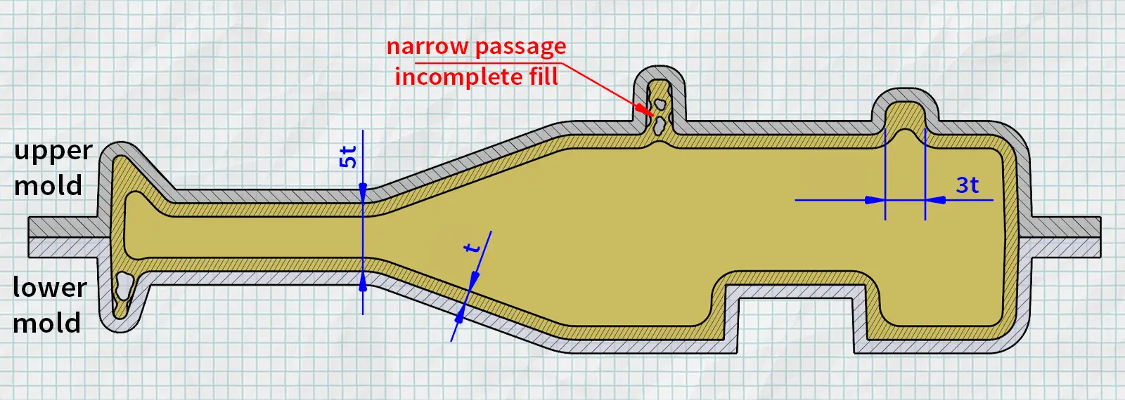
- There must be enough opening for the powder to move comfortably inside the mold. As a safe starting value, the distance between mold surfaces should be at least 5 times the target wall thickness.
- Narrow throats and passages where powder cannot move comfortably should be avoided. In such regions, the required clearance depends on depth and geometry; approximately 3 times the wall thickness may be accepted as a lower limit. Otherwise, the mouth of the opening may close prematurely and the region may remain underfilled.
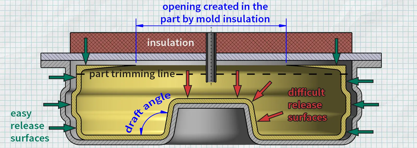
- In rotomolding, the part naturally forms as a hollow and closed shape. However, certain surfaces in the mold can be isolated so that they do not receive heat, preventing the plastic from coating those regions. In addition, the product can be cut at suitable locations after demolding to become single-wall.
- The outer surface of the part directly takes the form of the mold’s inner surface. The inner surface, however, does not form with the same precision; it is shaped according to the free spread of the molten plastic inside the mold. For this reason, especially narrow channels, recesses, and similar details cannot preserve the same clarity and openness on the product interior as they do on the exterior.
Transitions and Corners
In rotomolding, geometry should be as smooth as possible; abruptly broken transitions and sharp corners may negatively affect both material behavior and part quality.
- Smoother and more controlled transitions help the overall part come out more balanced.
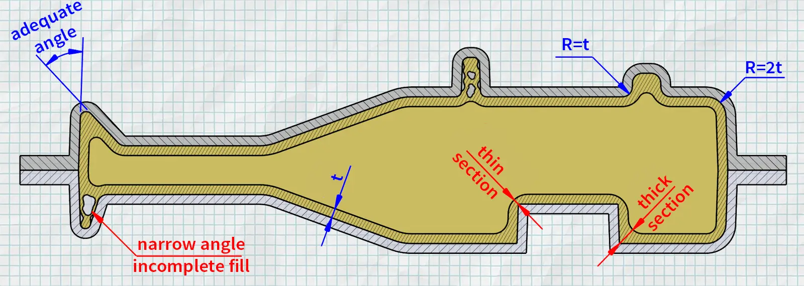
- Sharp corners should be avoided. Since material does not distribute evenly in corners during rotomolding, inner corners tend to become thinner while outer corners tend to become thicker.
- Unless corner radii are intentionally limited for another design purpose, they should be kept as large as the design allows. As a practical lower limit, inner corner radii should preferably not fall below the wall thickness, and outer corner radii should preferably not fall below 2 times the wall thickness.
- When they create narrow regions, corner angles should be kept as wide as possible. As the angle becomes smaller, the corner becomes tighter and it becomes harder for the plastic to coat that region properly.
- Corner decisions made without considering the relationship between inner and outer surfaces together may create unwanted weak regions in the part.
Surface Stiffness and Reinforcement Details
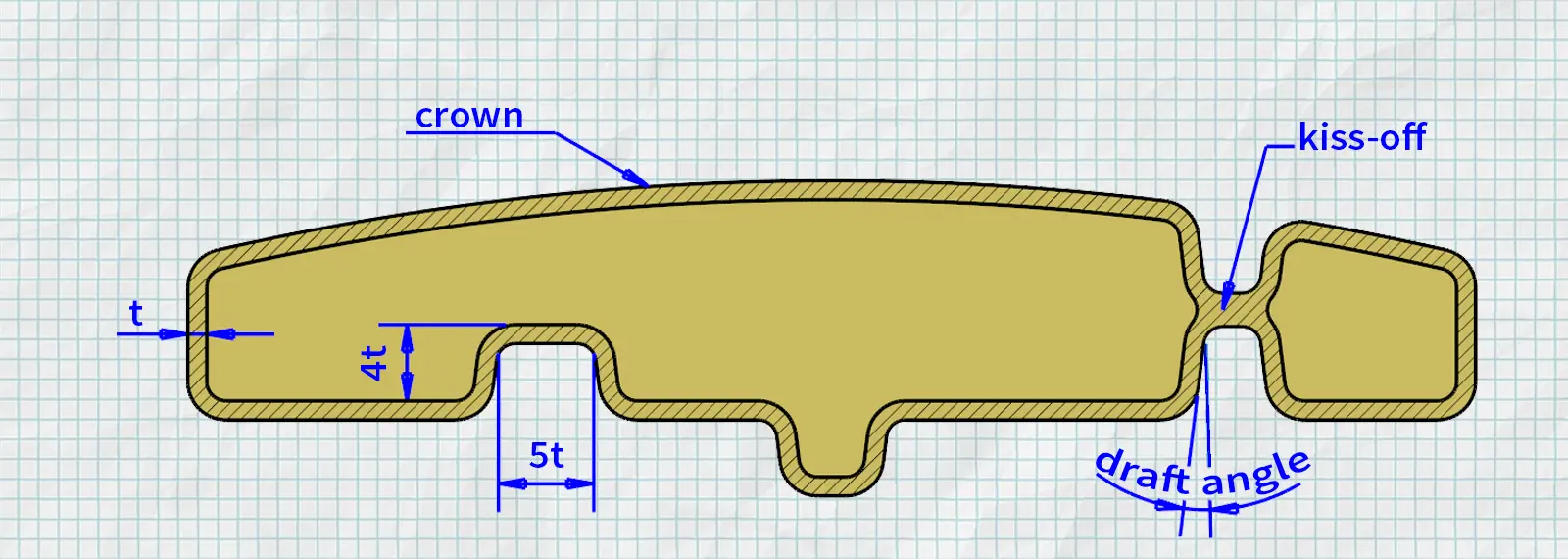
In rotomolding, reinforcement details such as ribs, beads, kiss-offs, domes, and surface breaks, especially used to increase stiffness and strength on large and flat surfaces, should be considered as a natural part of the design. However, these details must be designed in line with the flow logic of rotomolding.
- A dome is one of the most effective ways to increase surface stiffness. If possible, the surface should be given a curvature of at least 1.5%.
- In rotomolding, ribs should be considered not as solid features like in injection molding, but as hollow reinforcement elements.
- Whether ribs are directed inward or outward should be determined according to the functional, structural, and geometric requirements of the relevant region.
- As a practical starting ratio, rib depth should be considered at least 4 times the wall thickness, and width at least 5 times the wall thickness.
- Increasing rib depth increases stiffness, but as depth increases, molding and heating may become more difficult.
- Draft angle should be given to rib side walls to facilitate release from the mold.
- For greater strength, kiss-offs that act as bridges between surfaces or walls may be used. These supports are preferred to increase part stiffness and reduce flexing.
Demolding and What Comes After
Geometry should be evaluated not only according to the shape that will form in the mold, but also according to how it will be removed from the mold and what will happen to the part afterward. The part’s release from the mold, whether cores will be required in certain regions, and which forms will be cut or drilled afterward due to the closed volume logic should all be determined already at the design stage.
- In regions where the plastic pulls away from the mold while cooling, the part may still come out of the mold even without draft angle. In fact, in some geometries, details that would normally seem locked can still release without using cores thanks to this shrinkage. (Such as the beads used in vertical cylindrical water tanks.)
- In these regions where the plastic separates from the mold and shrinks freely, final dimensions and tolerances may be less predictable compared to other surfaces.
- In regions where the plastic forms by wrapping around protruding mold surfaces, the part pulls/shrinks toward those surfaces while cooling. For this reason, sufficient draft angle should be provided especially on such surfaces.
- In regions where the part shrinks by wrapping around protruding mold surfaces, dimensional behavior is usually more controlled, so dimensions and tolerances are generally more predictable.
- In cases where geometry causes the plastic to shrink toward the mold and grip the part, it should be considered in advance on which side the part will be retained in a controlled way. Retaining surfaces or similar guiding solutions can be designed on the opposite side to allow easier release.
- Since the material rotates and forms inside a closed volume, the natural form of a rotomolded part is a closed and hollow body. Therefore, if a single-wall product is desired, the part should be cut open afterward or the relevant region of the mold should be isolated so that it does not receive heat.
- For the same reason, some openings, mouths, holes, and similar details desired on the product are obtained afterward by operations such as cutting, drilling, or milling. In some cases, however, such details can be formed directly by using devices added to the mold that prevent the plastic from wrapping those regions. Guide marks can also be left in the mold for regions that will be machined afterward.
- Thanks to the same closed-volume logic, insulation foam can later be injected into the internal volume in some products. In some cases, a self-foamed structure can be achieved during the process, so the product is produced directly as foamed.
- When necessary, additional parts can be mounted onto the product afterward or during production. Polymer add-on parts can be joined by welding; metal parts can be inserted while the product is still hot. In some cases, add-on parts are fixed directly to the mold, and during production the material is allowed to wrap these parts and lock them mechanically.
- The vent point should be selected at the location that best evacuates gas. However, since a hole will form there, it should, if possible, be placed in a region that will already be drilled/cut later or will remain unseen. If this is not possible, how that hole will be closed afterward should be determined during the design stage.
Is Your Geometry Really Suitable for Rotomolding?
If you have doubts about pockets, flat areas, transitions, cores, or demolding in your current design, we can evaluate the part together according to rotomolding logic.